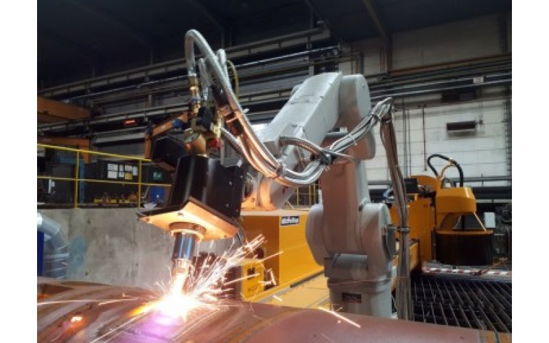
Production of pressure vessels and boilers counts among the major industrial applications where cutting of 3D objects comprises an essential part of the production process. The obvious requirement is to make this process fast, simple to setup and, most importantly, with an accurate result that won´t need further mechanical or even manual processing. Typical cutting tasks in this regard are cutting of openings in a dished end of a vessel for welding of inlet pipes, slicing of a dished end or trimming of the edges of a dished end with preparation for its welding to the vessel body. The cross-sections of the cut edges must meet the requirements of the subsequent welding process – in other words, depending on the wall thickness of the cut object, the V-, X- or K-cuts with constant or variable bevels need to be produced with the prescribed accuracy, preferably in a fully automatic process.
 |
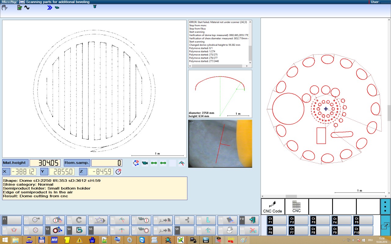 |
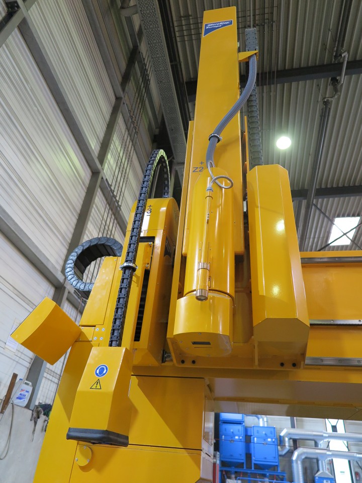
For such tasks MicroStep has developed a special beveling tool station that enables tool tilting up to 120° while having a big enough stroke to reach across the whole dome surface. Furthermore, MicroStep has newly introduced an advanced 3D laser scanning process and a corresponding point cloud mapping software – mSCAN – that enables a CNC cutting machine to measure the true shape of a 3D object, e.g. a dome, and use this measurement for adjustment of the subsequent cutting process so that contours and openings are cut in the needed positions on the surface with a very high precision – compliant with the production requirement.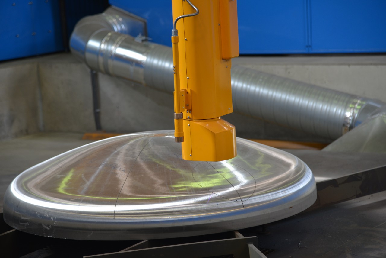
Needless to say, implementation of such 3D scanning technology greatly contributes to increasing of the accuracy of the dome cutting process, as the real dimension of a dome can lay within – at least – allowed tolerances which in fact means that the real and ideal shapes of domes sometimes differ by several centimeters. Conventional methods of positioning corrections via control of plasma arc voltage are thus not applicable in case of 3D cutting. Implementation of a scanner on the other hand makes it possible to create a model of the actual dome surface within the coordinate system of the cutting machine and to subsequently use this model to analyze the shape of the dome, identify its center and define the exact toolpath above the surface. How does it work?


